Is a plate within a plate that can make more plates a MetaPlate?
Who knows, but that’s the name of this test.
What’s the Objective?
With the rise of Virtual Production, notably LED volumes and a shortage of familiar artists with real-time engine experience, we’ve seen plate material doing a lot of work in these stages.
Shooting plates is a sure win for the photo-realism question. We’ve gained some brilliant results displaying live-action imagery inside an LED volume but it has its limitations. For example, the parallax is fixed and you can only capture from one camera vantage point, at a time, unless you bring lots of cameras.
For this test, I’ll capture two shots: a high-resolution 2D cine plate and nest it inside a bigger 360° still plate.
Independently, both plates have their use in the traditional VFX world; a large cine plate provides great resolution to “punch in” but is limited to a single POV. A high-resolution HDRi 360° is useful for backgrounds, DMP (Digital Matte Painting) assets and can be down-sampled for use in an Image-based lighting pipeline.
Putting the two techniques together offers a starting point for virtual backgrounds that can exploit the full advantages of shooting inside an LED volume.
There are a few hurdles to overcome to create this simple test, namely, capture, line-up, colourspace and delivery. Once a workflow is established I can tinker with other ideas, for example creating some 2.5D depth and the addition of CG and extra DMP elements.
To summarise, these are the key objectives:
- What’s the scope of using a still image for a background in an LED stage?
- Does creating very high dynamic range imagery pay dividends in an LED volume?
- Is there scope to enhance the 2D image into a scene that has depth, allowing basic camera movement?
The Capture
We used two different cameras positioned on the same nodal point, anchored to a powered, programmable head that could repeat two different motions.
The first programme used a Canon 5DS R + EF Lens to capture 819 images from 17 positions. Each position captures seven exposures, two stops apart. When stitched, it creates one, still, Equirectangular image (also called a LatLong) with 79k x 39k of resolution and 13 EVs, delivered in ACES.
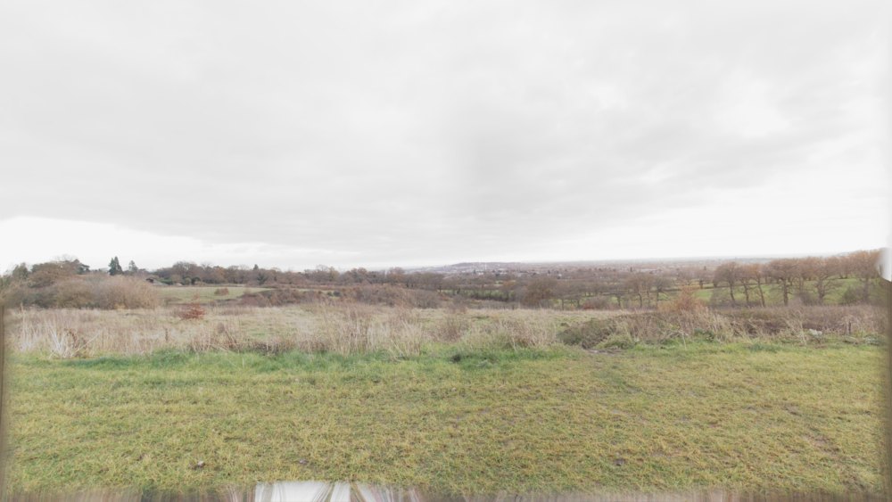
The second shot used a Black Magic 12K URSA + EF Lens to capture four 10-second clips from a tiled, top right to bottom left, programme. When stitched together, it creates one 10-second 20k x 11k, cine plate delivered in ACES.
The Scene
We chose a high viewpoint across London on a clear, sunny winter’s day because it was quickly accessible. However, what might work better could be an inaccessible extreme location such as on top of a highrise building or within an arctic landscape.
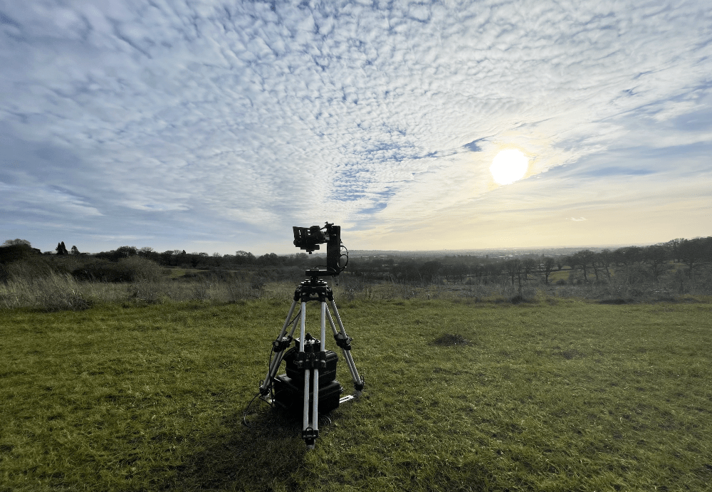
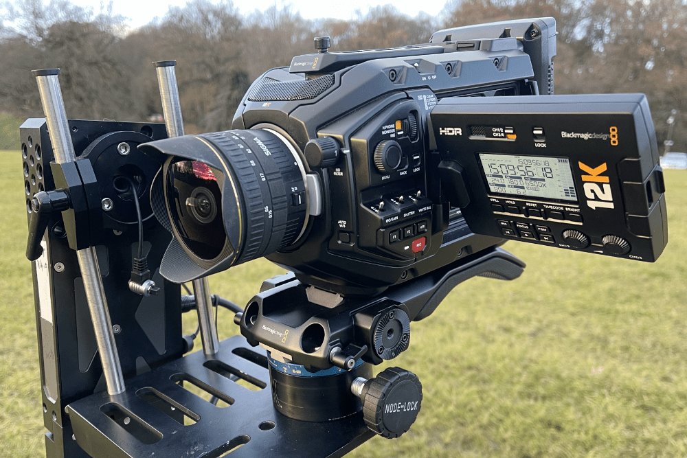
The Process Steps
- Shoot two image sets from the same nodal position with minimal time between them;
- Post-process the component images and stitch them into two single plates;
- Create a 3D scene and project the LatLong onto a sphere;
- Carefully position the stitched cine plate into the pano and attempt to create a seamless match;
- Playback the results on an LED wall.
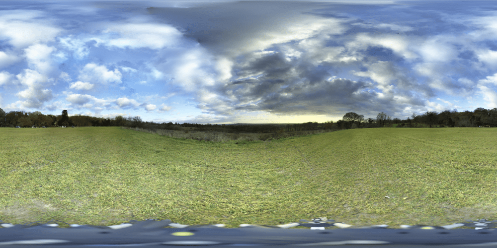
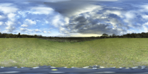
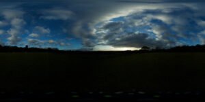
Colour Matching
It’s worth noting, although, outside the scope of this blog, it’s an important step to get the CR2s and BRAW matched in colour. To do this I used the ACES framework.
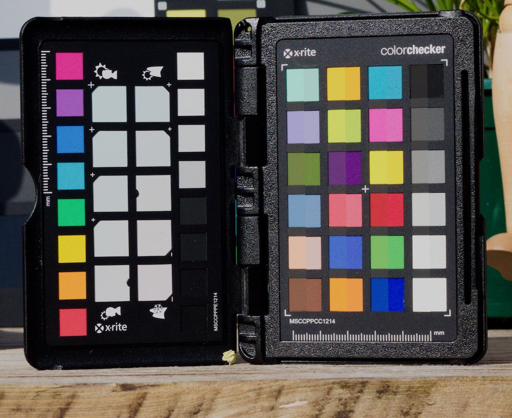
Both image sets were processed into ACES 2065-1 and compared in ACEScg. Both cameras shot a test chart and were matched by lens, speed and ISO, outside in daylight.
If you look at the right-hand patches on the image below, you’ll see a split on each wedge. On the left side is the Canon, and the right is the BM. The results are close.
Alignment
After processing the two image sources I end up with a 20k rectilinear cine plate and a 79k Equirectangular still plate.
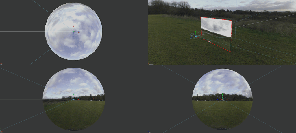
The first exercise is to set up the 3D scene with a sphere and the 360° projected within. The 2D plate sits on an image plane and is adjusted so that it aligns with a vCamera that sits in the centre of the ball.
At this point, the two images are graded to match each other; making the nesting of images as seamless as possible.
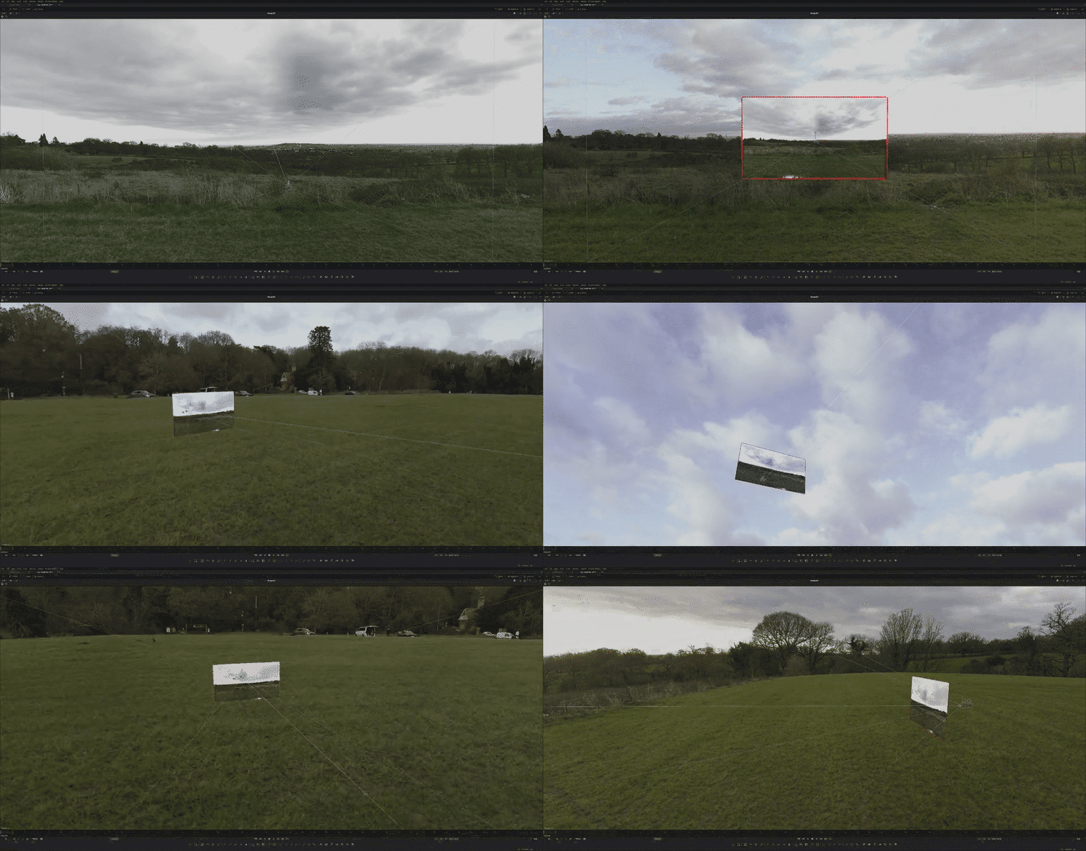
In the future, I’ll pay some thought into the edge blending. The example below shows a simple rectangular mask applied to the cine plate with heavy feathering to create the transition from one image to another.
The scene is rendered from the vCam centred in the ball as a rectilinear image. The match isn’t bad however, there are some tonal changes around the edges, mainly from the moving clouds.


A more complex technique and perhaps something that could provide some basic parallax is to split the images into layers working with depth planes. Now that the main cine plate is aligned splitting it into layers is fairly trivial. For example, split the trees from the sky and separate them in Z to create distance from one another. A sense of parallax can be achieved with this method.
However, once you’re on this path, projection makes more usable sense and is more sophisticated but requires an extra step of geometry creation. This could be hand modelled in a DCC or a mesh created from a LiDAR scan that would have been performed at the same capture time.
I’ll cover these techniques in a future post when we’ve gathered the right data at the acquisition stage.
What’s next?
Now the comp is set up and cached (it’s big!) some thought can go into how it can be used and what type of deliverables can be made.
At this stage, it’s still a 2D photograph with a “cine frustum”. It has an obvious use for LED stages because the project contains all the imagery needed to create an immersive scene. Its lack of motion needs some further testing with an introduction of comped CG (using the scene to light the CG) and perhaps the collection of more cine material around the circumference of the scene.
It’s well suited to provide many different shots by panning or tilting the vCamera. However, if the cine plate isn’t framed it will essentially be still. If the shot is focused on the FG then the BG should naturally fall away, in turn, it’s going to be less relevant than it’s still. If that scares you, then some light grain matching and some simple CG (a windy tree or such) could keep it alive.
On the delivery front, there is enough real estate to create a wide range of images that can cover curved screens, flat screens, projection, etc. For curved volumes, a typical delivery resolution has been 16k x 2k with an additional 2k square ceiling piece. This is easily achieved because the source res is so big and can be “re-photographed” to provide the extra components needed for different stage configurations.
As for light contribution, utilising the high dynamic range of the still has yet to be seen. We’ll be performing some tests on stage very soon.
What have I learnt:
- A capture workflow and how the cameras should be mounted
- Matching colours with a CR2 and BM RAW – a workflow has been created
- Stitching and aligning different plates inside one another
- A delivery workflow for a professional ACES output
The holy grail is a photographic 360° scene with depth to enable some camera tracking. Hopefully, I’ve started that ball rolling; next, stop quick depth creation (if it exists).
